Scan to AutoCAD takes one step: open the DXF your 2Dscanner exported, the same way you open any drawing. It comes in at real size, with each scan as its own block and everything sorted on layers that start with 2DS_.
The work on site and the other export files are covered in our 2D scanner for CAD guide. This page starts at the moment you have the DXF on your computer.
What is inside a 2Dscanner DXF?
| Comes from | The 2DscannerPro App or the 2Dscanner Editor. Both write a DXF. |
|---|---|
| DXF version | AutoCAD 2007 DXF |
| AutoCAD versions | Opens in every AutoCAD version from 2007 on, on Windows and Mac |
| Units | Stored in the file (mm, cm, m or inch) |
| Layers | All start with 2DS_. Which ones appear depends on what you choose to export. |
| Blocks | One per scan, named SCAN_number_time |
| Openings | Windows and doors measured with the ERA1D are drawn on the plan |
| Points | Polylines where points form a line, single points for the orphans |
| Images | Photos and ERA1D measurements, as image references |
| Colors | Fitted lines red, point polylines blue, or ByBlock if you switch it on |
Scan to AutoCAD, step by step: how do you open the file?
- Open the file. Type
OPENand select the DXF. - Bring it on screen. Type
ZOOM, thenE. - Save as DWG. Use
SAVEASso you work in a proper drawing and keep the DXF untouched as your measured original. - Tidy the layers. Freeze the ones you do not need and lock the rest (table below).
- Turn the plan to your grid. The easiest way is before export: the app and the Editor can both rotate the plan so that a wall runs along the X or Y axis. In AutoCAD, use
ROTATEwith theReferenceoption.
What does each 2DS_ layer do?
| Layer | What it holds | What to do with it |
|---|---|---|
2DS_LINES | Straight lines fitted to the corrected points, reduced to the horizontal and joined at the corners | Keep on and lock. This is what you trace. |
2DS_POINTS | The corrected points: polylines where they form a line, single points for the orphans | Keep on to check a fitted line against the real wall, for example around a bulge or a radiator. |
2DS_NOTES | Text notes and stickers placed on the scan | Keep on while drawing. |
2DS_OPENINGS | Windows and doors measured with the ERA1D, drawn on the plan | Use them as they are. They are drawn the way architects draw openings. |
2DS_MEDIA | Your photos and ERA1D measurements, as image references | Keep on while drawing. |
2DS_ORIGIN | Where the 2Dscanner stood | Freeze, or keep to see which position measured what. |
2DS_SIGNAL | Signal quality, shown as yellow circles. High values mean a poor measurement. Both the app and the Editor can leave it out completely. | Turn on when a wall looks wrong, otherwise freeze. |
The Editor can also export 2DS_RAW_ layers, without the tilt correction. You almost never need them: when you tilt the scanner on purpose, for example for a vertical scan, the app recognises it and applies no correction anyway. They help only in rare cases, such as a scan deliberately tilted by a few degrees, or a scan on a boat that moves slightly.
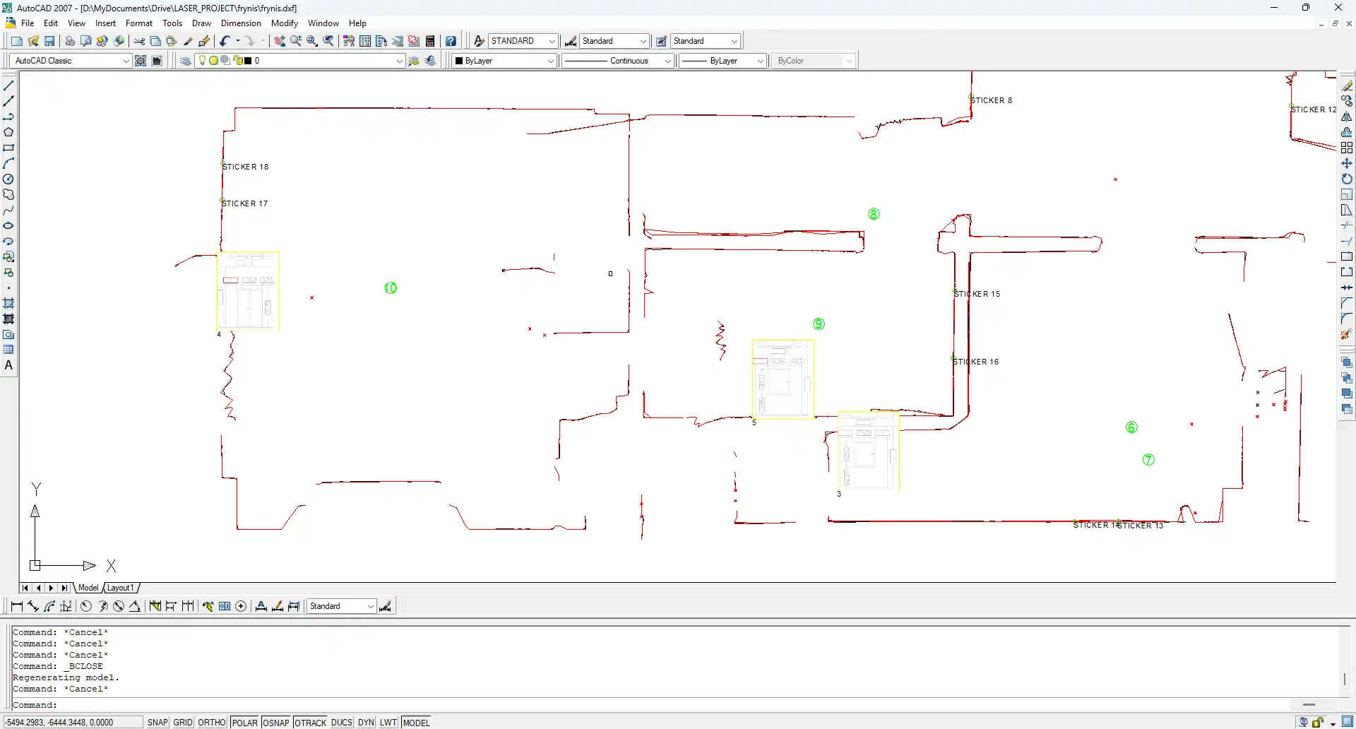
A typical file looks like this:
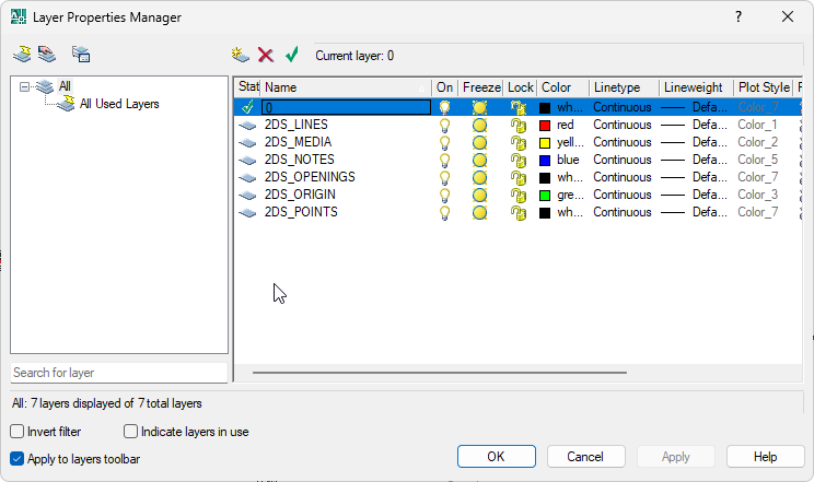
Layers apply inside blocks as well, so freezing 2DS_POINTS once hides the points of every scan. Object snaps still work on locked layers. The scan is a reference: you draw your own lines over it, so the 2DS_ layers normally stay out of the print, except perhaps 2DS_OPENINGS. Set the rest to No Plot (the printer icon in the Layer Manager) and they stay on screen without printing.
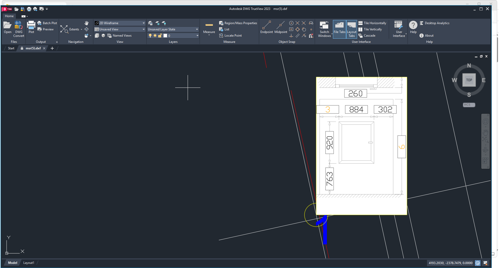
How are the scan points stored, and how do you change the way they look?
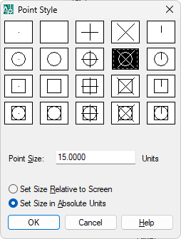
Points that belong to a line are joined into polylines. Orphan points, the ones with no line to belong to, are exported as plain AutoCAD points. By default they appear as a circle with an X.
To show them differently, type DDPTYPE (Format > Point Style) and choose a symbol and a size. It applies to every point in the drawing. If nothing changes on screen, type REGEN.
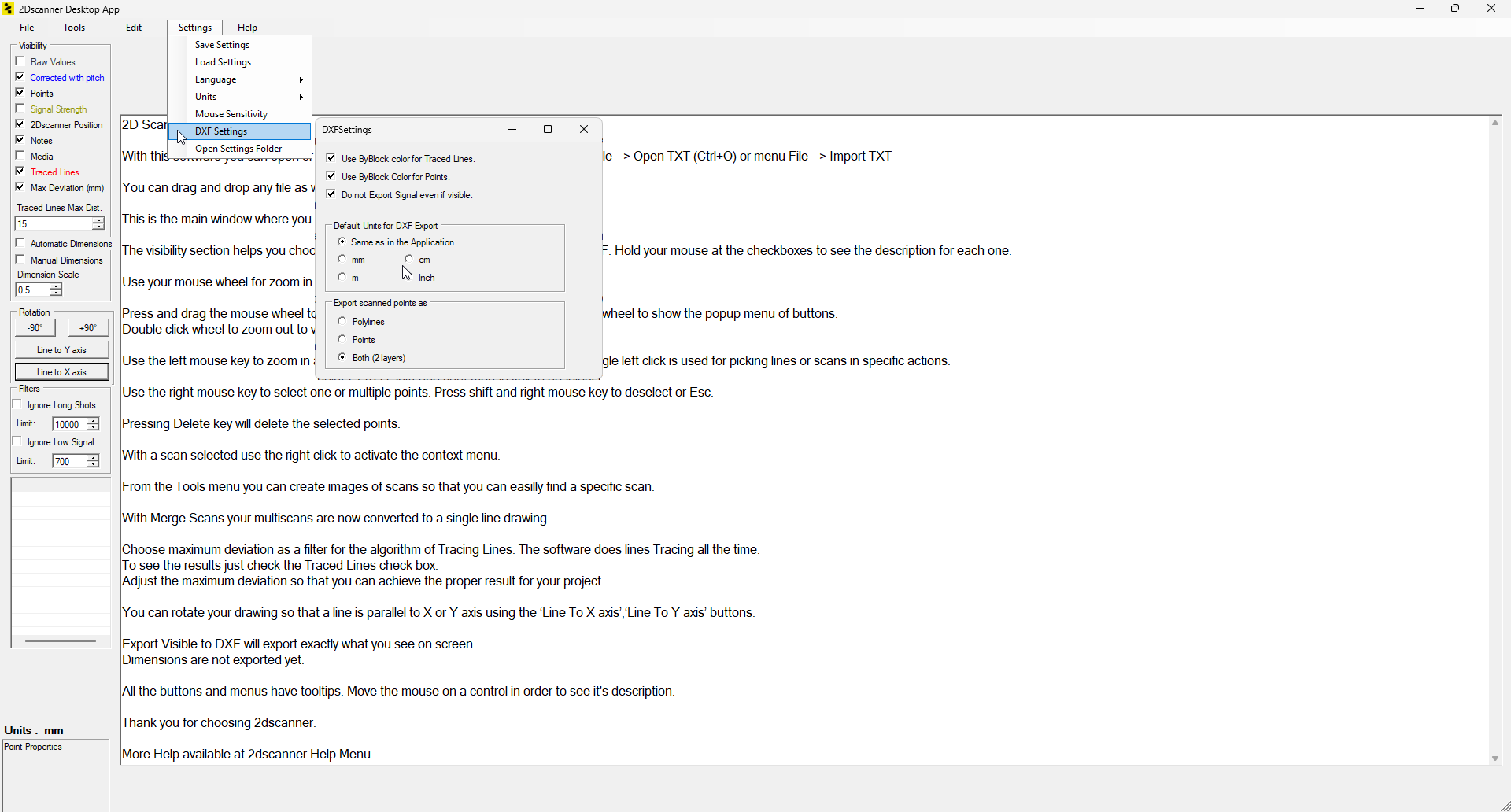
You also choose what gets exported, in the app and in the Editor. In the Editor it is Settings > DXF Settings > Export scanned points as. Polylines gives polylines on the lines and points for the orphans, Points gives points only with no polylines, and Both puts the two on separate layers.
How do you work with the scan blocks?
Each scan is one block, so one click selects it and MOVE or ROTATE takes the whole scan with it. Its name, in the form SCAN_number_time, is in the Properties palette (Ctrl+1).
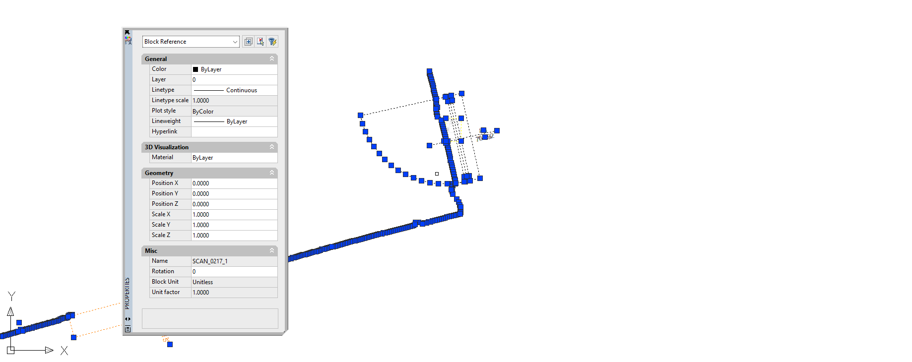
Correcting something inside a scan. To change the contents of a block you have two choices. BEDIT opens the Block Editor and the scan stays one block. EXPLODE also works, but the scan stops being one object and ByBlock lines turn white.
Cleaning up is faster in the Editor. It has tools a CAD program does not: you delete points directly, and it draws new fitted lines when you do, with no block editing. Then export again with File > Export Visible to DXF. Only what is visible on screen gets written, as the File Menu page explains.
Give each scan its own color. In the same DXF Settings of the Editor, tick Use ByBlock color for Traced Lines and, if you want, Use ByBlock Color for Points. Export again, select a scan in AutoCAD and change Color in Properties. The whole scan follows. With three positions in three colors, you see at once where two scans disagree about a wall.
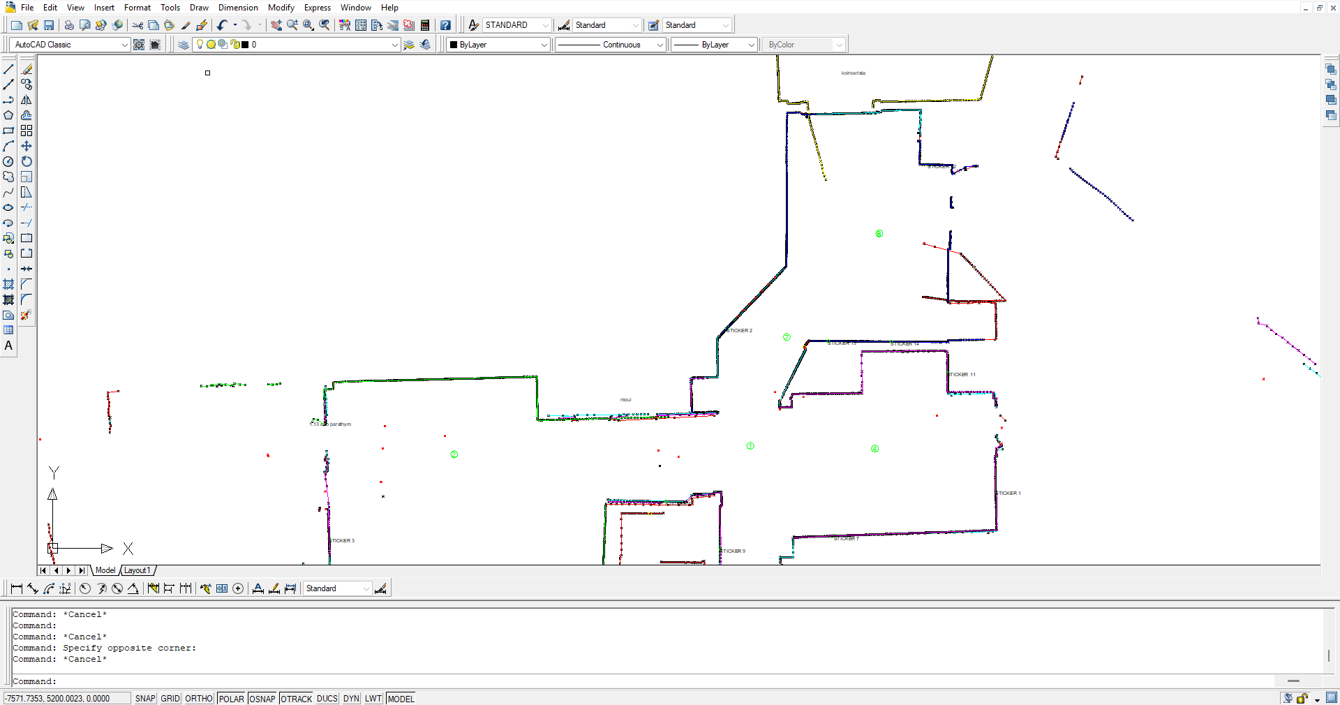
Bringing a scan into a project drawing. Open the DXF, select everything, press Ctrl+C and paste into your project with Ctrl+V. The SCAN_ blocks arrive as they are, and the time in each name keeps them from clashing with scans from other files. If you use INSERT instead, the whole DXF comes in as one outer block, and one EXPLODE releases the scan blocks inside it. AutoCAD converts the units for you when both drawings have their units set; if your project drawing is Unitless, set its units first.
Joining scans. Do it in the app or the Editor when you can, since they align on corners, stickers or two straight lines. If two scans reach AutoCAD separately, use ALIGN on two points that both scans can see.
What does the scan give you for drawing the walls?
Draw your walls on your own layer over 2DS_LINES. Endpoint snap catches the corners of the fitted lines. Two things you no longer have to measure: between two joined rooms, the gap between the lines of the two scans is the real wall thickness, and windows and doors measured with the ERA1D are already on 2DS_OPENINGS.
To reuse the fitted lines directly, NCOPY copies them out of the block and leaves the block whole. If your version does not have it, copy the block and explode the copy.
Why does the scan look wrong in AutoCAD?
| What you see | Likely cause | Fix |
|---|---|---|
| Empty screen after opening | The view is not on the drawing | ZOOM, E |
| Empty squares instead of photos | The file is open in the Editor or another program, and AutoCAD cannot read the images | Close it in the other program and open it again in AutoCAD |
| Room is tiny even after Zoom Extents | A few long shots through a door or window stretch the drawing | Zoom in on the room. To drop the far points before they reach AutoCAD, use Ignore Long Shots, in the app while scanning or in the Editor |
| Drawing is crowded or slow | All the layers are on, with thousands of vertices | Freeze 2DS_POINTS and 2DS_SIGNAL |
| A layer is missing | It was not chosen for export, or the element was hidden in the Editor | Choose it in the app or the Editor and export again |
| Points are missing along a wall | The Editor filters removed them from the DXF | The TXT file keeps every point. Open it in the Editor, relax the filters and export again |
FAQ
Does this work in AutoCAD LT and AutoCAD for Mac?
Yes. Both open the same DXF, and blocks, layers and ByBlock color behave the same way.
Can I attach the scan as an Xref?
Yes, once it is saved as DWG. XATTACH does not take a DXF directly.
Can I dimension straight from the scan lines?
Yes. Snap to the ends of 2DS_LINES with DIMLINEAR or DIMALIGNED. The combined accuracy is ±2 mm within a 7 m radius, on walls the laser meets at more than 34°.
Do my handwritten notes come through to AutoCAD?
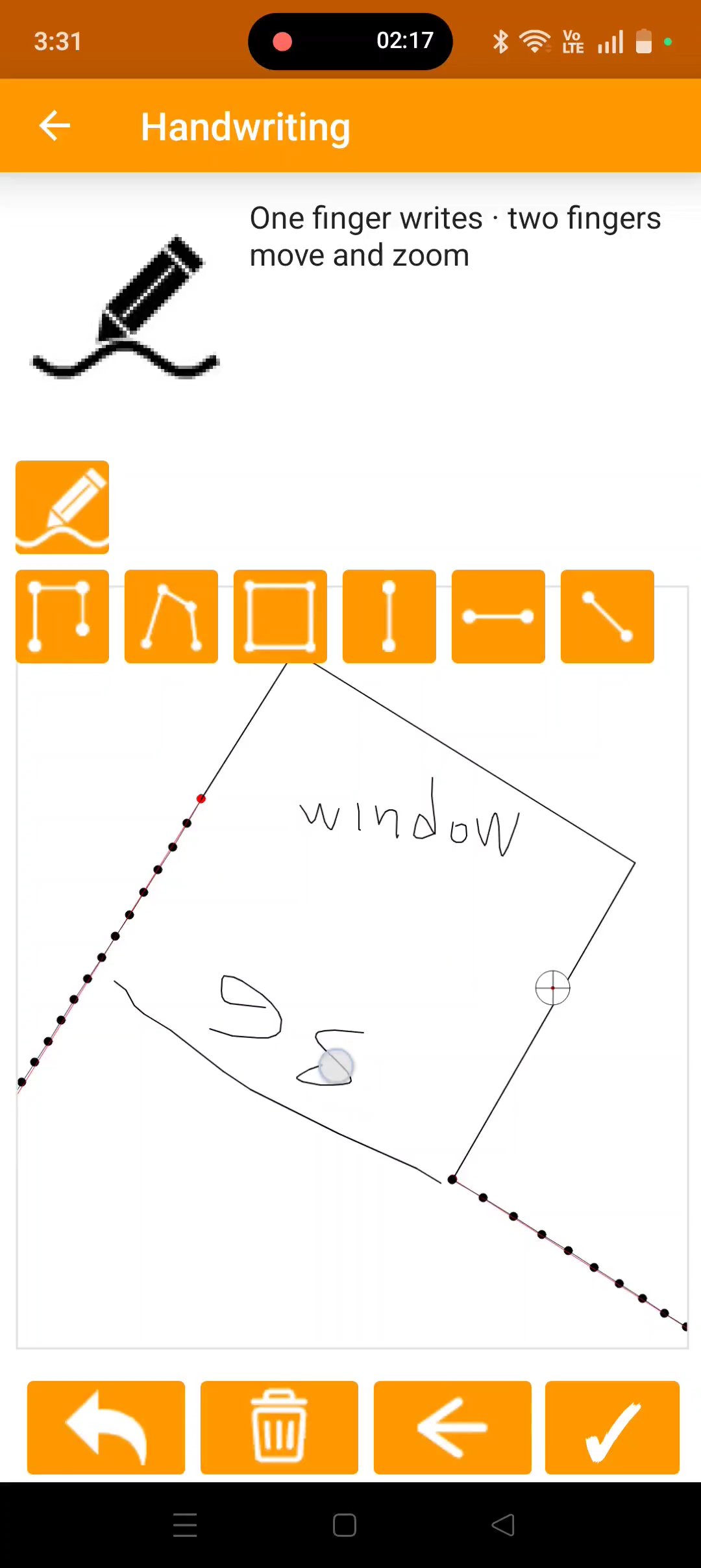
Yes, as polylines on 2DS_NOTES, at the same position and scale as the drawing. See how to add handwritten notes to a scan.
Try it yourself: download the sample 2Dscanner DXF (ZIP, from the plan at the top of this page) and follow the scan to AutoCAD steps above.
Every plan on this page was measured with the 2Dscanner EVO. One scan takes about four minutes and gives you the room as a DXF that opens straight in AutoCAD. No tape, no diagonals, no redrawing from a sketch, and no subscription.
If you want to stop measuring by hand, see the 2Dscanner EVO and what comes with it.
For every setting of the 2DscannerPro App and the Editor, step by step, see the 2Dscanner help pages.