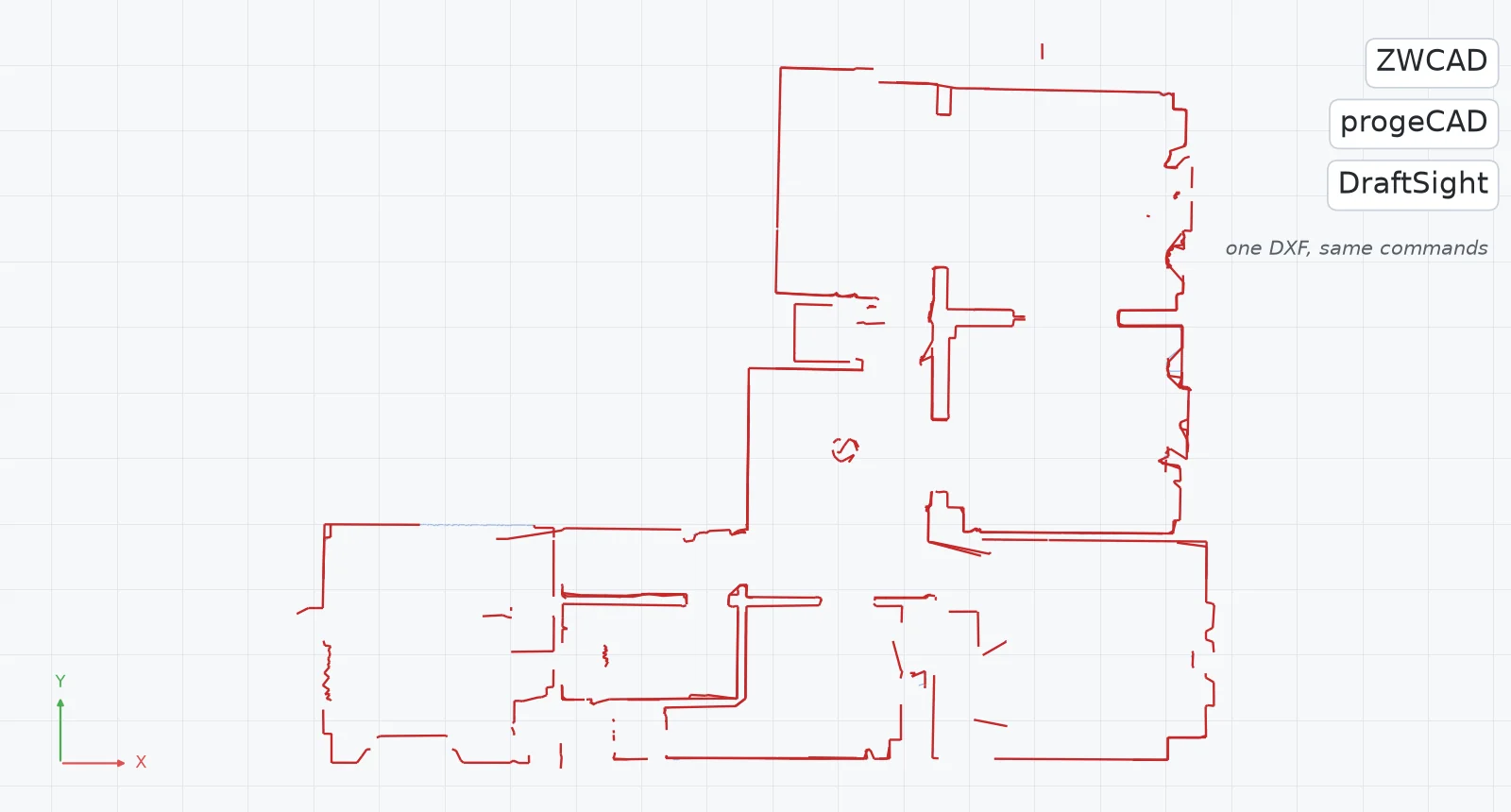
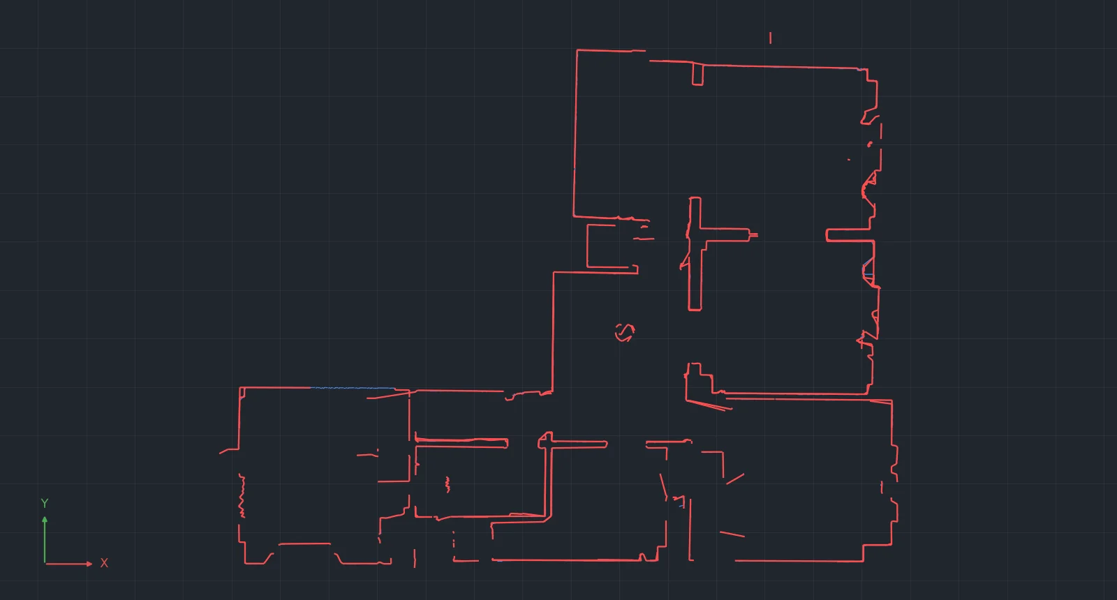
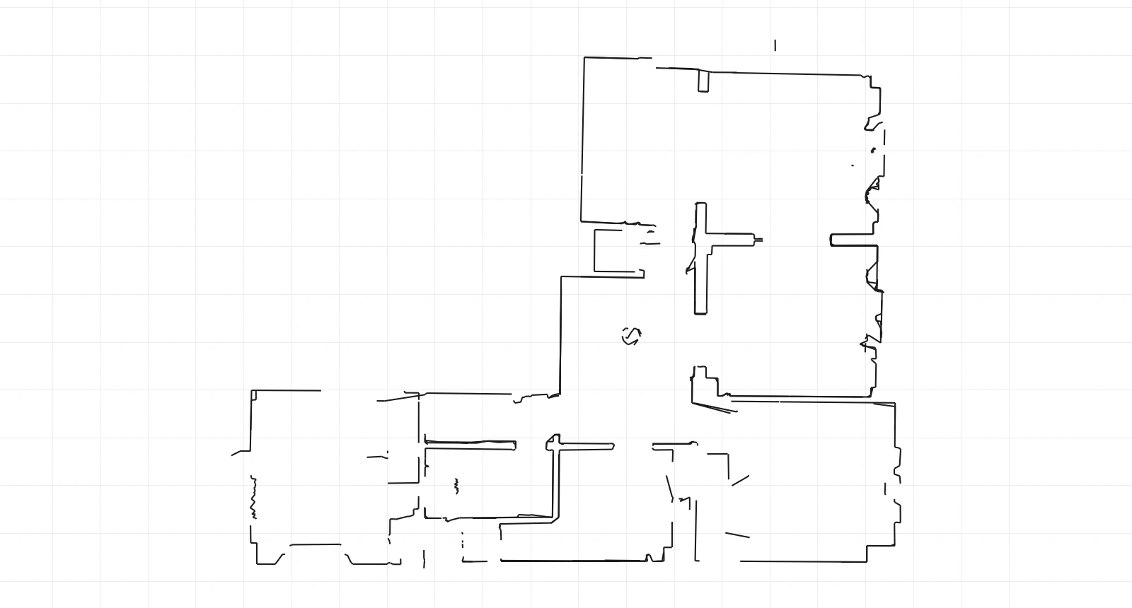
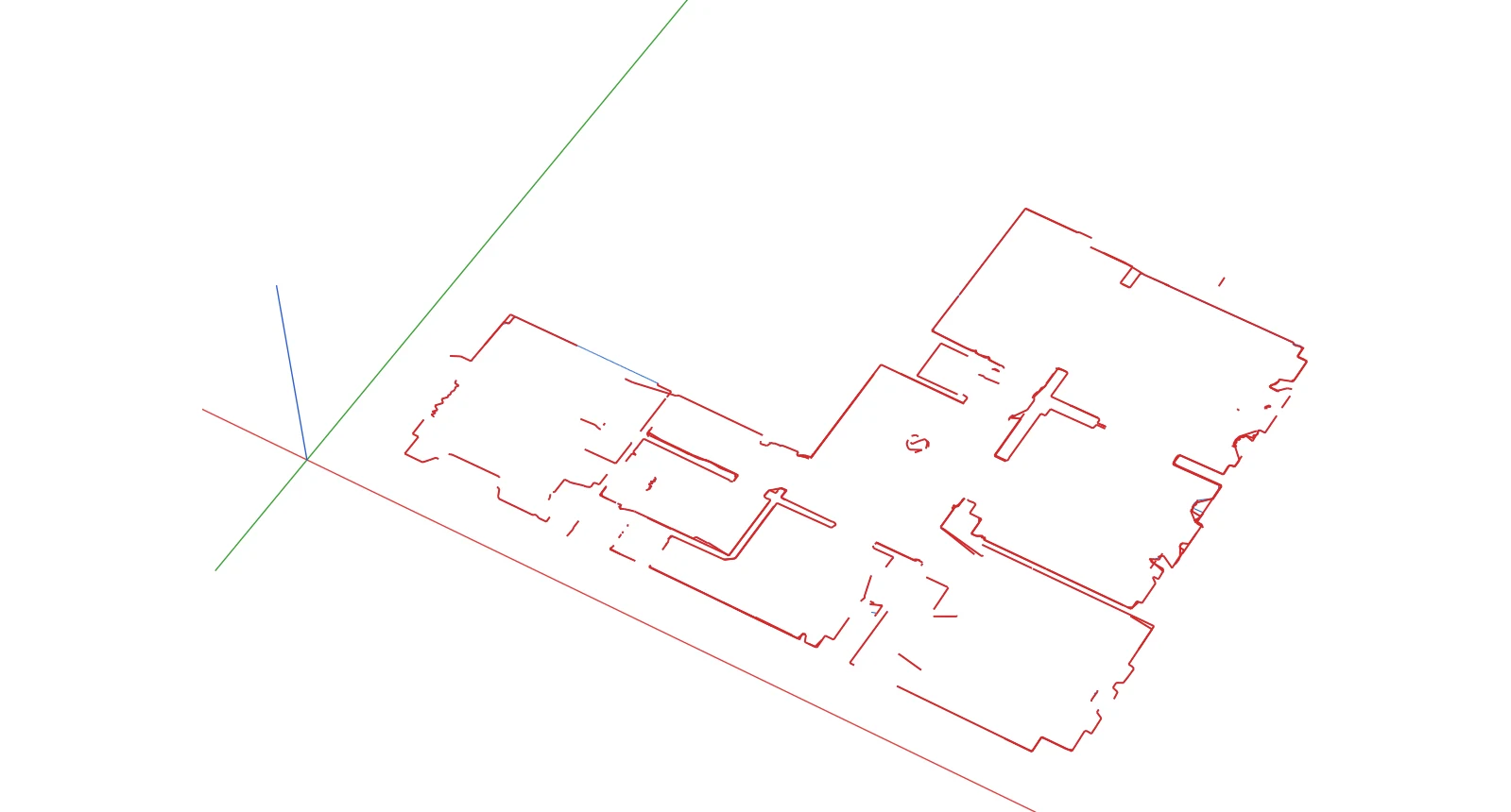
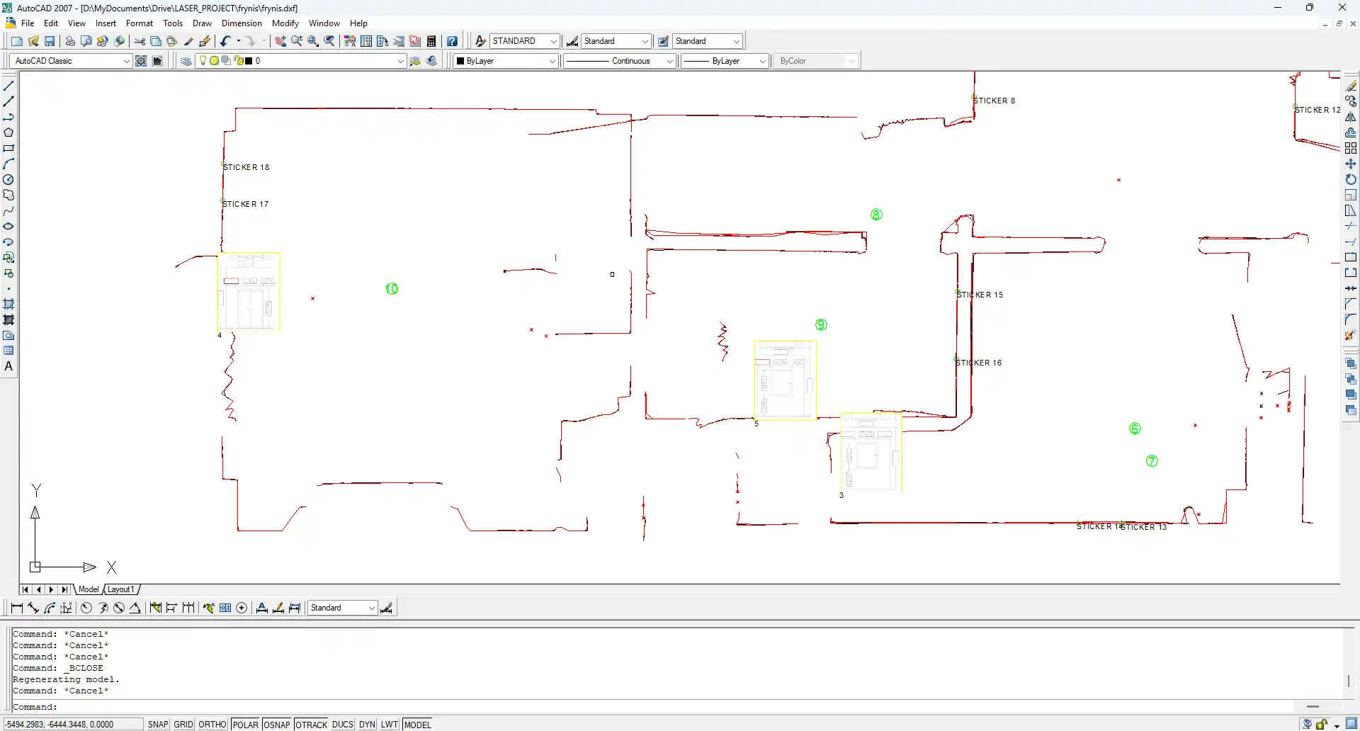
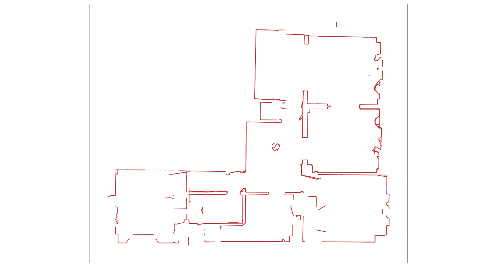
To import a DXF into Revit, open a floor plan view and use Insert > Link CAD, with the import units set to the unit of your export. The 2Dscanner plan comes in at real size as one underlay, and you draw Revit walls on its lines with Pick Lines.
The work on site and the other export files are covered in our 2D scanner for CAD guide. This page starts when the DXF is on your computer and ends with Revit walls on the measured lines.
Link or import?
Link. Autodesk recommends linking in most cases, and for a scan it is the better choice: the DXF stays a clean measured reference, it does not add its layers to your project as new categories, and if you clean the scan again in the Editor and export over the same file, Reload in Manage Links brings the new version in.
Use Import CAD only if you want to explode the scan into Revit lines. The options below are the same for both.
How do you import a DXF into Revit, step by step?
- Open the floor plan view of the level you are modelling, for example Level 1.
- Select Insert > Link CAD and choose the DXF. Set Files of type to DXF if you do not see it.
- Tick Current view only, so the scan shows in this plan and not in 3D or sections.
- Colors: Preserve keeps the red fitted lines and the blue points apart. Black and White is calmer if you only trace.
- Layers: choose Specify and keep only
2DS_LINES,2DS_OPENINGSand2DS_NOTES, or keep All and hide the rest later. - Import units: choose the unit you exported in, for example millimeter. The DXF stores its unit and Auto-Detect should read it, but setting it yourself costs nothing and rules out a plan 1000 times off.
- Untick Correct lines that are slightly off axis. It straightens lines that are almost horizontal or vertical. On a design drawing that helps; on a survey it hides the real angle of a wall.
- Positioning: Auto – Origin to Origin keeps several files of the same building aligned. Use Auto – Center to Center if the plan lands far from your project.
- Click Open, then type
ZEto zoom to the whole plan.
The plan is easier to work with if a wall already runs along the X or Y axis. The app and the Editor can both rotate the plan that way before export.
What does the 2Dscanner DXF become in Revit?
| In the DXF | In Revit |
|---|---|
| The whole file | One import instance, selected with one click |
The 2DS_ layers | Layers of that instance, under Imported Categories in Visibility/Graphics |
Each scan, a block named SCAN_number_time | A nested import inside it, which appears as its own object after a Partial Explode |
| Fitted lines, polylines, notes | Lines and text you can snap to |
| Orphan points and photo references | May not appear. Neither is needed for walls; the photos stay in your export folder. |
What each 2DS_ layer holds is explained in our Scan to AutoCAD guide. To hide layers, type VG, open the Imported Categories tab, expand the DXF and untick 2DS_POINTS, 2DS_ORIGIN and 2DS_SIGNAL. To see which layer a line is on, select the scan and use Query.
How do you draw Revit walls on the scan?
- Pin the scan (select it, then Pin), so it cannot move while you work.
- Start the Wall tool (Architecture > Wall) and choose the wall type.
- Set Location Line to Finish Face: Interior in the Options Bar. The scan measured the inside face of each room, so this puts the face of the Revit wall on the measured line and the thickness grows outwards.
- Choose Pick Lines in the Draw panel and click the
2DS_LINESof each wall. If the wall comes out on the wrong side, press the spacebar to flip it. - Close the corners with Trim/Extend to Corner (
TR), where the scan has gaps at doors or furniture.
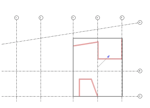
Between two scanned rooms you do not need to guess the wall thickness: the gap between the lines of the two scans is the real thickness, so choose or make a wall type that matches it. Windows and doors measured with the ERA1D are already on 2DS_OPENINGS, at their real position and width, ready for placing Revit doors and windows.
Keep the scan visible until the end. It is your measured reference, and Measure or a dimension between the scan line and the wall face shows any difference at once.
How do you work with the scans inside the DXF?
Revit holds the whole file as one import, with each scan nested inside. On a linked file you cannot change anything, which is what you want for a survey.
If you imported the file and need the scans apart, select it and choose Partial Explode: each SCAN_ block becomes its own import, which you can move, hide or delete. Full Explode turns everything into Revit lines and text, but Revit refuses it above 10,000 elements, which the point polylines of a large scan can exceed.
Cleaning up points is faster in the Editor, where you delete points directly and the fitted lines are redrawn, as the File Menu page explains. Export over the same file and reload the link.
Why does the import look wrong?
| What you see | Likely cause | Fix |
|---|---|---|
| Nothing in the view after Open | The plan landed outside the view, or Current view only was ticked in another view | ZE. Link it again from the floor plan view you work in |
| Plan is 10, 100 or 1000 times too big or too small | Import units did not match the export unit | Select the scan, Type Properties, set Import Units to the right unit |
| Plan is far from the project | Origin to Origin kept the position of the scanner | Move it, or link again with Auto – Center to Center |
Room is small even after ZE | A few long shots through a door or window stretch the drawing | Zoom in on the room. To drop the far points before export, use Ignore Long Shots, in the app while scanning or in the Editor |
| Walls look slightly skewed | The plan is not aligned to the project axes | Rotate before export in the app or the Editor, or rotate the link once in Revit |
| Full Explode fails | More than 10,000 elements | Hide 2DS_POINTS and use the link as it is, or Partial Explode |
FAQ
Does this work in Revit LT?
Yes. Revit LT has the same Link CAD and Import CAD commands and the same options.
Can I link the DXF in a cloud or workshared model?
Yes. With Current view only ticked the link belongs to the view; without it, to a model workset. Keep the DXF in a folder every user can reach, or Revit cannot reload it.
Should I use the scan for the ceiling height?
No. A scan is a horizontal slice of the room, so it has no height. Type the ceiling height you measured on site into the walls’ top constraint.
Should the walls on the scan go in the Existing phase?
Yes, if your project shows existing and new work. Draw them in a view whose Phase is Existing, or set Phase Created to Existing in their properties, so your phase filters show them as existing, demolished or new. For the full survey routine on site, see our measured survey guide.
Why is my linked DXF not showing in Revit?
First try the fixes in the table above. If the view is still empty, open Visibility/Graphics (VG), go to the Imported Categories tab and check that the DXF and its 2DS_ layers are ticked, and that a view template is not hiding imported categories in that view.
How accurate are the walls I draw?
As accurate as the lines you pick. The combined accuracy of the 2Dscanner is ±2 mm within a 7 m radius, on walls the laser meets at more than 34°.
Do the guides for other programs differ?
Only in the import step and the wall tools. See our guides for AutoCAD, SketchUp, Archicad, BricsCAD and ZWCAD, progeCAD and DraftSight.
Try it yourself: download the sample 2Dscanner DXF (ZIP, the plan at the top of this page) and import the DXF into Revit with the steps above.
The plan on this page was measured with the 2Dscanner EVO. One scan takes about four minutes and gives you the room as a DXF that Revit links at real size. No tape, no diagonals, no redrawing from a sketch, and no subscription.
If you want to stop measuring by hand, see the 2Dscanner EVO and what comes with it.
For every setting of the 2DscannerPro App and the Editor, step by step, see the 2Dscanner help pages.